Utilizing a straightforward passive component to merge or divide DC and RF signals may seem simple in theory, but its execution involves numerous nuances.
Operating in the realm of RF frequencies ranging from hundreds of megahertz to gigahertz, the RF world is replete with unique components. Some are specific to higher frequencies, while others manifest at lower frequencies with varying component sizes and physical structures.
The bias tee (sometimes denoted as bias-T) is a commonly employed RF component that finds occasional application at lower frequencies as well. This FAQ will delve into the functionality of the bias tee and the intricacies associated with its design and construction.
Q: What exactly is a bias tee, and what purpose does it serve?
A: The bias tee functions as a passive, bidirectional device with dual complementary uses: combining DC power and high-frequency (RF) signals into a single port (RF and DC), or splitting a combined RF and DC signal into its individual components. While sometimes referred to as a power combiner or splitter, it is important to note that the RF signal should not be confused with a power-line AC signal but rather recognized as an RF signal.
Q: Can you provide a basic schematic diagram of a bias tee?
A: A bias tee is depicted as a three-port device comprising only two passive components: a DC-blocking capacitor and an RF-blocking inductor (commonly known as a choke), as illustrated in Figure 1.
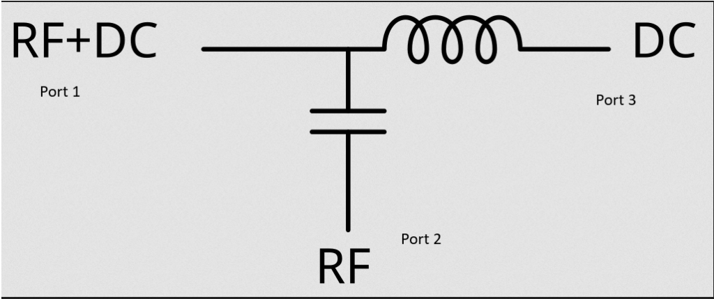
Figure 1. The schematic diagram of a bias tee encapsulates its fundamental simplicity. (Image: Wikipedia)
Q: How does a bias tee operate?
A: By leveraging basic electrical principles that have been utilized since the inception of electronics and electricity. To divide the combined RF and DC energy at Port 1, the capacitor obstructs all DC power transmission to Port 2, permitting only the RF signals to pass. Concurrently, the inductor in the circuit blocks all RF signals from reaching Port 3 but facilitates the passage of all DC power to that port. The process is elegantly straightforward.
Conversely, for the function of signal combination, the paths are reversed, with incident energies appearing at Ports 2 and 3, and the output observable at Port 1, while the component operations remain consistent.
Essentially, a bias tee embodies a unique diplexer with an ideal capacitor enabling AC passage while impeding DC power (often termed bias voltage), and an ideal inductor obstructing AC while permitting DC flow. The nomenclature “tee” in the device’s name is derived from the diagram’s appearance rather than its operational functionality.
Q: Where is the bias tee typically employed?
A: One prevalent application involves powering the low-noise amplifier (LNA) at a satellite dish like a consumer VSAT (very small aperture terminal) for satellite TV or Internet access. By utilizing a coaxial cable that conveys both the RF signal and power, the bias tee eliminates the necessity for an additional cable run, thereby reducing costs and simplifying installation. Instead of requiring a distinct cable for power, the essential power is “superimposed” onto the coaxial cable transporting the RF signal.
Q: Are there other applications for the bias tee?
A: Yes, several applications are less conspicuous or overt. Bias tees find utility within a system where an RF subcircuit necessitates a “bias” voltage for optimal operation (thus the moniker “bias tee”). By employing a bias tee, the same wire or circuit-board trace can cater to both requirements, thus facilitating and streamlining layouts and mitigating layout constraints.
Q: Considering the simplistic schematic diagram with only an inductor and capacitor, does the bias-tee narrative conclude here?
A: In the realm of RF, practical implementation deviates from theoretical simplicity. The passive component values must be dimensioned to accommodate the anticipated frequency band and bandwidth, as well as power levels spanning from minute to substantial wattage. Furthermore, the inevitable parasitic effects, which are invariably present, must be considered.
Q: How does a narrowband bias tee differ from a wideband one?
A: Bias tees are engineered to operate across a spectrum of signal frequencies, with the reactances chosen to exert minimal influence at the lowest frequency. As the bias tee’s bandwidth expands, its values and parasitic elements acquire greater significance, necessitating careful consideration during design and manufacturing.
Q: What are the design ramifications of this predicament?
A: The implications are manifold. For instance, the inductor must not exhibit self-resonances at the operational frequencies, a challenging design constraint to satisfy.
Q: How can this aspect of wider-bandwidth performance be addressed?
A: Achieving wider-bandwidth performance necessitates matching the inductor to the target band. One approach involves employing a series of inductors with incremental values. However, this method comes with cost implications and introduces additional parasitic factors. While stringing together three or four inductors in series extends the bandwidth coverage, it also heightens the associated DC losses.
Q: Are there alternative solutions?
A: Resourceful engineers have turned to conical spiral inductors, which function electrically as a graduated sequence of inductors for different frequencies interspersed with parasitic capacitors, as depicted in Figure 2.
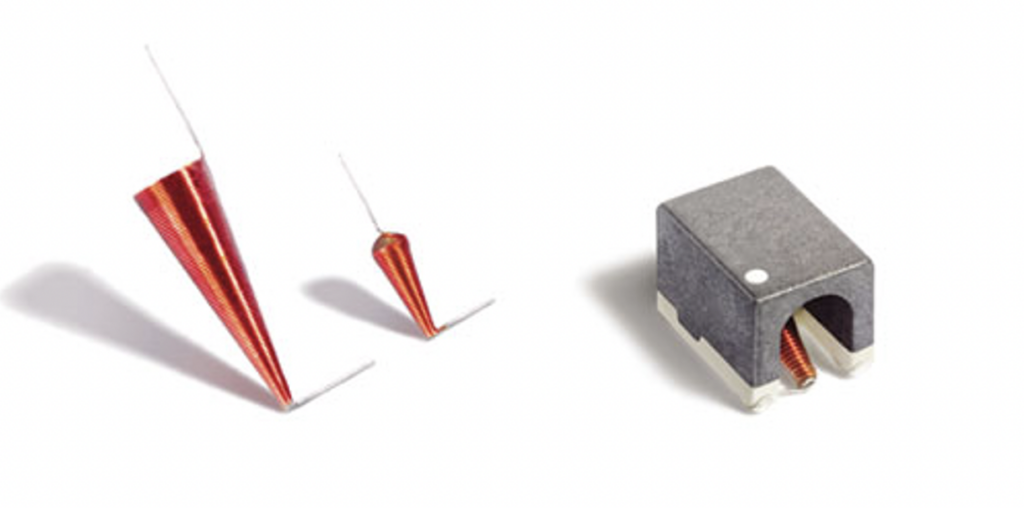
Figure 2. The conical inductor serves as a valuable addition to the arsenal of techniques employed to implement a wideband bias tee; (left) the rudimentary yet delicate “flying lead” version, (right) the inductor housed in a more robust surface-mount package. (Image: Coilcraft)
The conical structure mitigates the effects of stray capacitance and effectively engenders a series of narrowband inductors, resulting in high impedance across an extensive bandwidth. A solitary conical inductor can supplant a sequence of multiple narrowband inductors.
It is worth noting that conical inductors are not novel and have been utilized since the early days — Nikola Tesla incorporated them into some of his designs. However, mass production of these diminutive conical inductors is a contemporary development.
Q: Must designers personally engineer, model, and fabricate their bias tee units?
A: Certainly not. Despite their simplistic schematic and appearance, bias tees are intricate devices rife with subtleties. For instance, practical wide-band RF and microwave bias tees leverage specialized circuit topologies to circumvent the shunt path, which could impede performance. These bias tees integrate a series of inductors, additional capacitors, and resistors to avert resonances.
Q: What variants of bias tees are commonly utilized?
A: Bias tees are commercially procurable from numerous vendors, with some concentrating on a specific product range tailored to a particular class of applications, while others boast a diverse portfolio encompassing narrow RF bands, wideband systems, varying power levels, and a plethora of package types. The majority are either surface mount or feature solder pins, with connector options including SMA female, 2.4 mm, 2.92 mm, 3.5 mm, and Type N. (Traditional BNC and even SO-239 connectors are also obtainable.) Voltage ratings typically range from 24 to 100 volts, while maximum DC current spans from 200 milliamps to approximately 7 amps, although units beyond these ranges are also accessible.
Q: What packaging formats are employed for bias tees?
A: Packaging varies based on frequency range and power thresholds. Some are presented in compact shielded packages outfitted with diverse RF connectors, as showcased in Figure 3, while others manifest as diminutive surface-mount components. Even when employing unconventional components like conical inductors with flying leads, the complete bias tee is typically enclosed in a small plastic or epoxy casing for integration onto a printed circuit board (PCB), akin to other surface-mount technology (SMT) components.
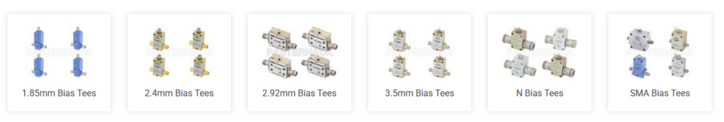
Figure 3. An array of commercial bias tee kits is available in diverse packages featuring various RF connectors (surface-mount packages not depicted). (Image: Pasternack)
Larger bias tees, measuring a few centimeters on each side and equipped with integrated RF connectors, typically bear connection details imprinted directly on their body, as evidenced in Figure 4. This contrasts sharply with the ambiguity associated with through-hole leaded and surface-mount ICs.
Q: How is impedance managed, a perennial concern in RF components?
A: Bias tees from commercial vendors are available in both 50-ohm and 75-ohm variants to cater to the distinct needs of the two RF application cohorts. The 50-ohm specification is predominantly employed in most wireless applications, while the 75-ohm standard is prevalent in numerous video-related and legacy applications.
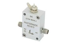
Figure 4. Numerous bias tee designs are sufficiently sized to bear schematic diagrams and connector functions prominently. (Image: Pasternack via Quora)
Q: What are the key parameters defining a bias tee for designers?
A: Designers contend with several parameters akin to numerous RF components:
- Lowest RF frequency
- Upper operating frequency
- Maximum RF input current
- RF insertion loss (dB)
- DC port isolation (dB)
- Power handling on each port
- VSWR
- Package style
Summary
Bias tees offer a seemingly basic yet immensely practical DC and RF functionality. Transitioning from conceptualization to physical realization poses a challenge, as is customary with RF devices. Vendors present an array of standardized units meticulously characterized across diverse frequency ranges, spans, power thresholds, and packaging selections. The references provided contain application insights and product details from select vendors.
References
RF/Microwave Bias Tees from Theory to Practice, Mini-Circuits
What is a Bias Tee?, Everything RF
Bias Tees, Spectrum Control
What is a Bias Tee Design concept?, Quora
Bias Tees (Bias Ts), Pasternack
Power-handling capabilities of inductors, Coilcraft
Solving RF Isolation Issues with RF Inductors, Coilcraft
What is a Conical Inductor?, Coilcraft
Bias Tee, Wikipedia