
Radomes play a crucial role in the world of wireless and RF communication. Whether installed on aircraft fuselages for radar systems or in automotive safety radar applications, radomes must be transparent to RF frequencies while providing protection from environmental elements such as wind, rain, snow, and motion.
Some radomes focus on protection, while others aim to minimize aerodynamic impact as well. The earliest radomes were developed during World War II using materials like plexiglass and fiberglass to protect radar and radio antennas on aircraft and reduce drag.
Over time, radomes evolved into distinctive shapes like the iconic “golf ball” design, which could house large antennas. Smaller radomes were also created using flexible fabric and pressurized air for rigidity.
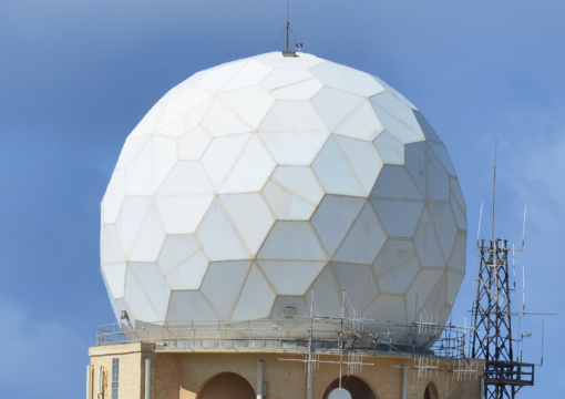
Figure 1. The popular image of a radome is a large sphere that resembles a golf ball. (Image: Milexia Products)
Radomes are now made from specialized materials and designed to blend seamlessly with the vehicle structure, such as in cars equipped with radar systems operating at 77 GHz. Each type of radome has specific attributes that make it suitable for its intended application.
This article will explore the material science and RF-related challenges associated with radome development, as depicted in Figure 2. While many issues apply to radomes of all sizes, some are more relevant to specific types of radomes.
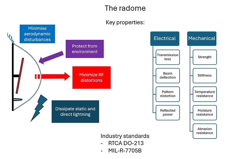
Figure 2. Despite its simple appearance, the radome actually has many technical requirements placed on it, along with electrical and mechanical constraints. (Image: The Engineering Pilot)
Although a radome may seem like a simple RF-transparent material, it serves a much more complex purpose.
It’s interesting to note that “radome” is a portmanteau word, combining “radar” and “dome” to form a new term. English contains many such blended words, like “smog” (smoke and fog) and “brunch” (breakfast and lunch). This is distinct from acronyms, which create new words from initial letters, such as “radar” from “Radio Detection And Ranging.”
Understanding the Electromagnetic Reality
A radome acts as a barrier between the antenna and its surroundings, ensuring RF transparency while protecting the antenna. While traditional radomes are often visualized as large white structures housing military or weather radar antennas, they are also widely used in consumer products and cell towers.
For a radome to be effective, it must not impede the transmitted or received waveform. Additionally, the reciprocity rule dictates that the same principles apply to both transmitted and received waves.
Materials and Layers
Several electromagnetic factors are crucial for an efficient radome, including material properties and layer thickness. When an EM wave encounters the interface between two dielectrics, reflection and refraction occur based on the permittivity of the materials involved.
Materials with higher dielectric constants result in stronger signal reflections, while conductors like metals exhibit very high dielectric constants and produce significant reflections. Polymers, with dielectric constants in the range of 2 to 4, reflect signals less strongly.
Optimal radome thickness occurs when the dielectric is reflectionless, achieved when the thickness is a multiple of half a wavelength. Material properties like dielectric constant and loss tangent play a significant role in minimizing signal loss in radome material selection.
The next part of this series will delve into geometry issues affecting radome design and performance.
Filed Under: Featured, Radar, RF