
Utilizing LC traps can transform a single-band dipole antenna into a multiband unit, making the long-wire dipole antenna an effective option for low-frequency systems.
Despite the prevalence of compact, high-frequency wireless devices today, the long-wire dipole antenna remains a valuable tool for various applications. Its versatility, portability, and effectiveness make it a popular choice among military, emergency services, broadcasters, and amateur radio enthusiasts for long-distance communication.
The long-wire antenna offers several advantages, including flexibility, easy setup, adjustable radiation pattern, low visibility, and compact size. While traditionally used in the high-frequency (HF) band below 30 MHz, it can also operate at higher frequencies. By adding traps to the dipole arms, a single antenna can cover multiple bands simultaneously.
Benefits of Using a Long-Wire Dipole Antenna
Maxwell’s equations dictate that an effective dipole antenna must have a primary dimension equal to half the wavelength of the desired frequency. The classic dipole antenna presents a balanced load to the transmitter and receiver, typically with an impedance of 73 Ω. Connecting it to a 50 Ω feedline requires an impedance-matching arrangement.

Figure 1. The basic, classic dipole antenna has two quarter-wavelength arms and appears as a 73-Ω balanced resistive load at its resonant operating frequency. (Image: MicrowaveTools)
A dipole’s bandwidth is typically around 5% of the center frequency and can be increased with thicker wire. A balun transformer may be necessary for grounded connections using coaxial cable. The antenna’s simple design allows for easy installation with minimal materials.
Adjusting the antenna length for optimal performance is usually straightforward, with performance often meeting expectations even without adjustments. The voltage standing-wave ratio (VSWR) is typically below 1.5:1, indicating good performance.
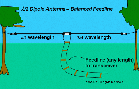
Figure 2. The dipole is usually attached to its supports via insulators(white) and added wire lengths, allowing the dipole arm lengths to be maintained independently of the distance between supports. (Image: Physics Forum)
Adjustments for optimal performance are typically minimal, with VSWR staying within acceptable levels. However, significant impedance shifts may require an antenna tuner for compensation.
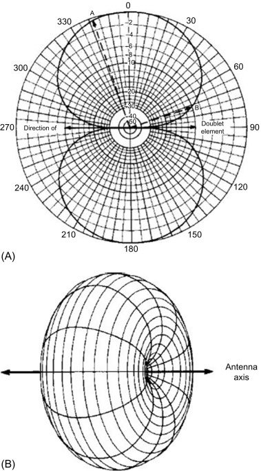
Figure 3. The radiation pattern for the horizontal dipole as viewed from a) above in the vertical plane and b) the side in the horizontal plane resembles a torus or donut. (Image: Science Direct)
Antenna orientation can be adjusted to maximize signal transmission/reception towards the desired target. Successful long-distance communication has been achieved using dipole antennas with minimal power output under suitable propagation conditions.
Enhancing Versatility with Multiband Operation
In real-world HF communication scenarios, establishing contact across multiple bands or switching between bands is often necessary due to various factors affecting connectivity. Setting up multiple dipole antennas for each band can be cumbersome, leading to practical challenges.
Traps provide a solution by acting as switches that enable multiband operation with a single dipole antenna. By inserting traps into each arm of the dipole, the antenna can cover multiple bands with a single physical length. Traps function as loading coils below the antenna’s resonant frequency and electrically isolate the antenna beyond the trap’s design frequency.
Figure 4 shows a simplified electrical model of the trap showing the physical inductor and capacitor and a small parasitic resistance.
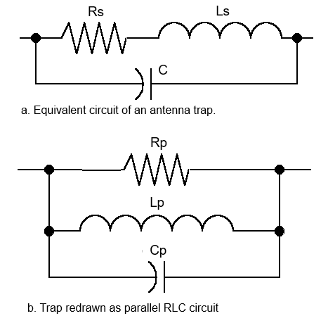
Figure 4. The trap is a simple, resonant LC circuit with some undesired, unavoidable resistance that can be modeled a) in series or b) as a parallel RLC circuit. (Image: AntenTop)
Traps are designed to introduce minimal loss, typically around 1 dB, enabling efficient multiband operation without significant compromise on performance.
Optimizing Trap Component Values
Choosing the right inductor and capacitor values for traps involves balancing resonant frequency, power handling, and ruggedness. Trap components must be rated for the power levels transmitted to ensure reliable operation.
Trap construction must consider weather exposure, requiring materials and sealing methods that withstand environmental conditions. Tuning trap components in the field may be necessary to achieve optimal performance.
Traps are not limited to simple dipole antennas and can be used in more complex designs like the Yagi-Uda antenna to enable multiband operation.
Conclusion
The enduring long-wire dipole antenna remains a valuable tool in wireless communication, especially when enhanced with traps for multiband operation. Its simplicity, adaptability, and effectiveness continue to make it a preferred choice for various applications.
References
Radio Antenna System, H.K. Morgan, U.S. Patent 2,229,865
Dipole Antenna, MicrowaveTools
Antenna Fundamentals: Radiation Pattern, Science Direct
Antenna Traps—A Way to Cope With Limited Space, On All Bands
Tuned Circuits and Traps, QSL Net
Modeling Trap Antennas, AntenTop
Multirange Trap Antennas, AntenTop
Low Cost Antenna Traps, VK4ADC’s web
Using Antenna Traps, SOTABeams
Related EE World content
FAQ on cable impedance: 50 Ω versus 75 Ω
What is “twin-lead” transmission line — and what happened to it?
How to use simple antennas for EMI troubleshooting
Demonstrating antenna diversity, Part 2: The PIFA
Demonstrating antenna diversity, Part 3: The Yagi antenna
What is a Smith Chart, and why do I need one? (Part 1)
Antennas and antenna measurements
What is a Smith Chart, and why do I need one? (Part 1)
5 tips for designing with embedded antennas
Filed Under: 5G antennas, FAQ, Featured, RF, RF filters, Sub-6 Ghz RF