Each of the three topologies of this versatile system building block has its place in modern systems.
The phase-locked loop (PLL) is crucial in various electronic systems and circuits, with a history dating back to the 1930s. It serves functions related to timing, clocking, frequency synthesis, synchronization, and signal recovery.
Despite being named a phase-locked loop, many applications focus on frequency rather than phase. The relationship between phase and frequency is intimate, as frequency is the time derivative of phase.
From an operational standpoint, the PLL functions as a phase-driven device, with its operation being driven by a phase difference. The term “phase” accurately reflects its operation compared to frequency.
This article will briefly discuss the original all-analog PLL, its successor, the digital PLL with analog elements, and the latest implementation, the all-digital PLL (ADPLL).
The article will not delve into operational details, as those are extensively covered in various sources. Instead, it will touch on issues associated with all-analog and hybrid PLLs.
For evidence of the PLL’s importance, the book “Phaselock Techniques” by Floyd M. Gardner, first published in 1966, remains a seminal work referenced in PLL analyses even today.
A brief history of PLLs
The first PLLs emerged in the 1930s using vacuum-tube technology to synchronize analog carriers. The transition to solid-state transistors reduced costs and enabled mass applications like color TV in the 1950s.
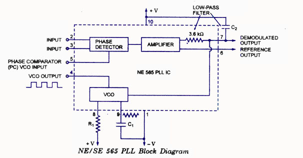
The NE565 PLL by Signetics Corp., introduced in 1969, was a landmark integrated PLL IC widely adopted for its performance and popularity.
Basic PLL operation (without equations)
The PLL functions as a closed-loop feedback-control system, typically employing a proportional-integral (PI) loop strategy. Various setup and performance issues impact PLL performance, necessitating detailed analysis.
The analog PLL comprises five key components, including the Phase/Frequency Detector, Charge Pump, Loop Filter, Voltage-Controlled Oscillator, and Frequency Divider.
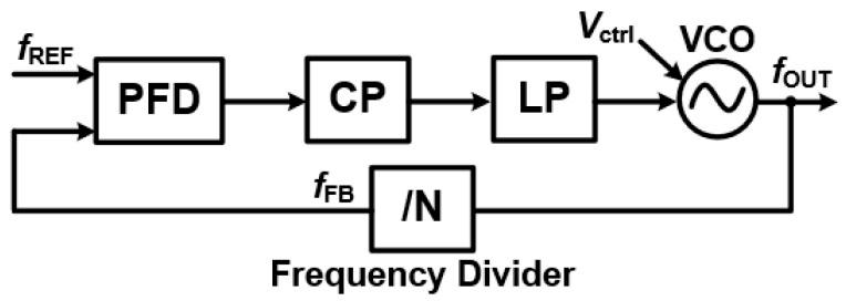
The loop filter, often a second-order passive-RC network, plays a crucial role in determining PLL dynamic performance to meet application requirements.
While the PLL’s other components aim for optimal performance, filter selection is critical due to the diverse choices available impacting PLL loop performance.
The article will explore digital PLLs and all-digital versions in the subsequent sections.
References
TUTORIAL: Phase Locked Loops, Integrated Device Technology, Inc.
ECEN620: Network Theory, Broadband Circuit Design, Texas A&M University
A Design Procedure for All-Digital Phase-Locked Loops Based on a Charge-Pump Phase-Locked-Loop Analogy, IEEE Transaction on Circuits and Systems
An Overview of Phase-Locked Loop: From Fundamentals to the Frontier, National Library of Medicine
Types of PLL in VLSI: Analog, Digital, and All-Digital PLLs, Success Bridge
Digitally controlled oscillator, Wikipedia
Three Major PLL Implementations, Movellus
Phase-Locked Loop (PLL) Fundamentals, Analog Devices
Signetics SE/NE 565 PLL Overview, Scribd
The Phase Locked Loop IC as a Communication System Building Block, Texas Instruments
Lecture 080 – All Digital Phase Lock Loops (ADPLL), Georgia Institute of Technology
Related EEWorld Online content
What is Proportional (PID) Control and why is it used? (Part 1)
What is Proportional (PID) Control and why is it used? (Part 2)
RCA & Color TV: A dominant company and standard, both now gone – Part 2
Does 32 kHz or 3.58 MHz mean anything to you? part 2
Synthesized tuning, Part 1: Basic frequency-synthesizer principles
Synthesized tuning, Part 2: Advanced synthesizers and performance
Filed Under: Communications, FAQ, Featured